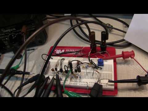
A detailed look at the 5 transistor ESR meter circuit designed by EEVBlog user Jay_Diddy_B. Here are links to a few threads on the EEVBlog forum that focus on this circuit:
http://www.eevblog.com/forum/projects/5-transistor-esr-meter-design/
http://www.eevblog.com/forum/projects/jay-diddy-5-transistor-esr-meter/
There is a lot of additional detail about the circuit contained in the above threads. The schematic can be found there, as well as a couple of PCB designs.
An ESR meter like this is designed to measure the equivalent series resistance of electrolytic capacitors – a common failure mode in consumer electronics. It works by applying a signal (100kHz square wave in this case) to the capacitor under test, and measuring the voltage drop across the device.
I really like this circuit – there are some very clever things going on. And, there’s some inherent beauty in solving a measurement need with a small handful of transistors. The circuit includes a very interesting emitter-coupled astable multivibrator, a measurement bridge, and an interesting capacitively coupled rectifing measurement circuit.

TIDRADIO TD-H3 5w Ham Handheld Radio, Long Range Two Way Radios with Type-C Programming and Aviation Antenna, Dual Band Radios with 2500mAh Rechargeable Battery(2 PCS) - Crystal case 1Pack
$46.99 (as of April 18, 2024 09:33 GMT +00:00 - More infoProduct prices and availability are accurate as of the date/time indicated and are subject to change. Any price and availability information displayed on [relevant Amazon Site(s), as applicable] at the time of purchase will apply to the purchase of this product.)![1️⃣[𝑪𝒖𝒔𝒕𝒐𝒎𝒆𝒓 𝑺𝒆𝒓𝒗𝒊𝒄𝒆]: If customers are not satisfied with the product, please contact us first. We will do our best to rectify the situation.We take responsibility for our products and customers.If you have any question please contact us through Ama...](https://m.media-amazon.com/images/I/51pomGpwt+L._SL160_.jpg)
(2 Gen) TIDRADIO TD-H8 Ham Radio 10W High Power Dual Band Two Way Radio,APP Programmable, Long Range Walkie Talkies Full Kits with 2500mAh Large Battery (2pcs),USB-C Charger & Speaker Mic,Green
$89.99 (as of April 18, 2024 09:32 GMT +00:00 - More infoProduct prices and availability are accurate as of the date/time indicated and are subject to change. Any price and availability information displayed on [relevant Amazon Site(s), as applicable] at the time of purchase will apply to the purchase of this product.)
BAOFENG UV-5R Ham Radio 8W Handheld High Power Dual Band 144-148/420-450Mhz Baofeng Radio Long Range Walkie Talkies with Programming Cable etc(Black+2Pack Full Set)
13% Off![✅[2nd Gen TD-H8 Ham Radio Handheld] This handheld two way radio features 10 watt output power, 2500mAh rechargeable battery and incredible 1.77 inches large color screen. And most importantly, TD-H8 is taking the lead of wireless programming, allow u...](https://m.media-amazon.com/images/I/41jMs-AtMnL._SL160_.jpg)
2nd Gen TIDRADIO TD-H8 Ham Radio 10Watt 2500mAh Battery Capacity Solid Performance Handheld Two-Way Radio Wireless Programming Module with Repeater List
$69.99 (as of April 18, 2024 09:22 GMT +00:00 - More infoProduct prices and availability are accurate as of the date/time indicated and are subject to change. Any price and availability information displayed on [relevant Amazon Site(s), as applicable] at the time of purchase will apply to the purchase of this product.)
(2nd Gen) TIDRADIO TD-H8 10Watt Ham Handheld Radio, Bluetooth Programming, Repeater Capable Dual Band Long Range Two Way Radios Walkie Talkies with 4PCS Batteries 771 Long Antenna -2Pack Full Kit
$149.99 (as of April 18, 2024 09:22 GMT +00:00 - More infoProduct prices and availability are accurate as of the date/time indicated and are subject to change. Any price and availability information displayed on [relevant Amazon Site(s), as applicable] at the time of purchase will apply to the purchase of this product.)
Baofeng UV-5R Ham Radio Long Range Two Way Radio UV5R Handheld Dual Band Walkie Talkies with Programming Cable Extra 1800mAh Li-ion Battery and AR-771 with Earpiece (Black-2Pack)
$55.99 (as of April 18, 2024 09:22 GMT +00:00 - More infoProduct prices and availability are accurate as of the date/time indicated and are subject to change. Any price and availability information displayed on [relevant Amazon Site(s), as applicable] at the time of purchase will apply to the purchase of this product.)
Walkie Talkies, MOICO Long Range Walkie Talkies for Adults with 22 FRS Channels, Family Walkie Talkie with LED Flashlight VOX LCD Display for Hiking Camping Trip (Orange 2 Pack)
7% Off
Emergency Weather Radio, Waterproof Bluetooth Portable AM/FM/NOAA Weather Radio, 5000mAh USB Hand Crank Solar Radio, Phone Charger, Flashlight, SOS-Red
$32.99 (as of April 18, 2024 09:25 GMT +00:00 - More infoProduct prices and availability are accurate as of the date/time indicated and are subject to change. Any price and availability information displayed on [relevant Amazon Site(s), as applicable] at the time of purchase will apply to the purchase of this product.)
commountain 3.5mm Listen Only Earpiece for Speaker Mic of Motorola Kenwood Baofeng etc, Acoustic Tube Receive Only Headset with 3 Earmolds, for Police Security and Law Enforcement Use
$10.95 (as of April 18, 2024 08:25 GMT +00:00 - More infoProduct prices and availability are accurate as of the date/time indicated and are subject to change. Any price and availability information displayed on [relevant Amazon Site(s), as applicable] at the time of purchase will apply to the purchase of this product.)
12000mAh Emergency Weather Radio Hand Crank Radio Solar Radio Portable AM/FM/NOAA Radio with 2 Solar Panels 3 Charging Methods SOS Alarm 3 Mode Flashlight Phone Charger Reading Lamp
$42.99 (as of April 18, 2024 09:21 GMT +00:00 - More infoProduct prices and availability are accurate as of the date/time indicated and are subject to change. Any price and availability information displayed on [relevant Amazon Site(s), as applicable] at the time of purchase will apply to the purchase of this product.)
Marxon U1 320CCA Riding Lawn Mower Batteries, Garden Tractors Battery Maintenance Free AGM Battery, Compatible with Troy-Bilt, John Deere, Toro, Cub Cadet, Craftsman, Ariens, Poulan Pro
$69.99 (as of April 18, 2024 09:21 GMT +00:00 - More infoProduct prices and availability are accurate as of the date/time indicated and are subject to change. Any price and availability information displayed on [relevant Amazon Site(s), as applicable] at the time of purchase will apply to the purchase of this product.)
10000mAh/37000mWh Emergency Hand Crank Radio,AM FM NOAA Weather Alert Radio, Digital Display,3 Ways Powered Hand Crank,Solar Radio with Type-C Charger,Flashlight,Reading Lamp,Headphone Jack,SOS Alarm
$42.99 (as of April 18, 2024 09:22 GMT +00:00 - More infoProduct prices and availability are accurate as of the date/time indicated and are subject to change. Any price and availability information displayed on [relevant Amazon Site(s), as applicable] at the time of purchase will apply to the purchase of this product.)